Silicon Controlled Rectifiers: A Retro Semiconductor Guide
▼ Summary
– The Silicon Controlled Rectifier (SCR) is a three-terminal electronic switch from the 1950s that latches on when a gate signal is applied.
– It consists of PNPN semiconductor junctions, with terminals designated as the anode, cathode, and gate.
– While once popular in the 1970s, SCRs are now often replaced by components like TRIACs and MOSFETs, though they remain in old schematics and are still available.
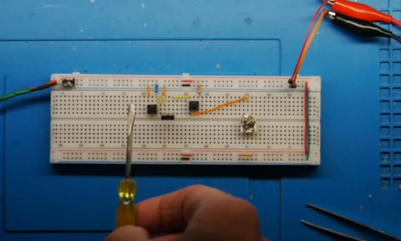
– A YouTube review by Lockdown Electronics demonstrates SCR usage, compares it to a TRIAC, and shows a 1977 windshield wiper circuit using SCR technology.
– The video’s demonstration with AC power had some lighting issues, but it covers the fundamental basics of SCR operation.
While modern power electronics often rely on TRIACs and MOSFETs, the Silicon Controlled Rectifier (SCR) remains a foundational component with a rich history. Invented in the 1950s and widely used through the 1970s, this three-terminal thyristor is a latching switch that continues to appear in legacy schematics and is still available for purchase today. Understanding its operation provides valuable insight into the evolution of semiconductor control.
The fundamental principle of an SCR is relatively straightforward. It features three terminals: an anode, a cathode, and a gate. The device remains in a non-conducting state until a brief trigger signal is applied to the gate terminal. This action allows current to begin flowing between the anode and cathode. Crucially, the SCR then latches into the “on” state, continuing to conduct electricity even after the gate signal is removed. The only way to turn it off is to interrupt or reduce the main current flowing through the anode and cathode below a specific holding threshold. This latching behavior is a defining characteristic.
Internally, the SCR is constructed from a silicon wafer arranged in a PNPN structure, forming three semiconductor junctions. The leftmost P-layer serves as the anode, the rightmost N-layer is the cathode, and the middle P-layer connects to the gate terminal. This specific arrangement is what enables the controlled rectification and latching action that makes the component unique.
In practical demonstrations, the SCR is often compared to a TRIAC, which is essentially a bidirectional version capable of controlling alternating current in both directions. A common application showcase for the SCR is in older control circuits, such as a classic 1977 automotive windshield wiper timing module. These circuits effectively utilized the SCR’s reliable latching characteristic to create intermittent timing functions, a testament to its utility in an era before microcontrollers.
For electronics enthusiasts restoring vintage equipment or studying historical designs, familiarity with the SCR is essential. Its role may have been supplanted by more advanced components in new designs, but its operational logic laid the groundwork for modern power switching. Recognizing how and why it was used offers a deeper appreciation for the engineering solutions of the past.
(Source: Hackaday)